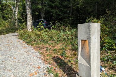
Sometimes when I’m browsing the web I get inspired by whatever it is I’m looking at. That so happened when I stumbled upon the following picture:

A small light post made out of concrete which houses a single spotlight that shines downward and scatters the light down on the ground. The description said it was easy to make a mold out of wood, and pour concrete in it. I think it would be great to have some small light posts at our cabin to light up the path from the parking area to the cabin. I imagined these kind of lights to fit really well in the area since they do not take up too much space, give a nice indirect glow of light low at the ground. I figured if I make them myself they hopefully would not get too expensive either.
Materials
Obviously, to make the mold I’d need some wood. I settled on cheap spruce wood for the vertical parts and some oak wood for the base purely because I had a piece laying around and it seemed a bit stronger. Additionally I bought:
- B30 concrete.
- Electrical tube.
- Electrical boxes.
- Brown & blue electrical wire.
- GU10 light holders.
- Fishing wire.
- 200mm bolts.
- Screw rods.
I learned that concrete is not to be confused with cement. Cement is an ingredient of concrete, which I found out whilst shopping for this project. I also learned that there are different types of concrete, indicated by the B-number. B30 is appropriate for outdoor use, hence why I went for this.
The 200mm bolts stick out of the bottom of each light and will act as an anker once I mount the lights at the cabin. The screw rods I figured would act as some cheap form of reinforcement. The fishing wire is to keep the electric tube and screw rods in place while pouring the concrete.
Since I’d be making a reusable mold I’d decided to try and make 6 light posts. Why 6? I don’t know, it just felt right.
The build process
The building process of the mold was fairly straight forward. I’d labelled all the sides (A, B, C & D) and made sure to use 3 screws between all sides to firmly hold them together in a square. Side A would hold the diagonal piece and cut-out for the lightbulb, whilst side C would hold the electrical box.


The sides mount on top of a base plate using a total of 8 screws. I also used some foam in between the base plate and the sides to try and make them watertight and thus prevent concrete from leaking out while it was drying.

Cross section of mold before pouring the concrete
The screw rods are hanging in the mold with the use of fishing wire, and run most of the length from top to bottom. The electrical box and tube are held in place using hot glue. After everything was screwed and glued together I mixed the concrete in small batches (~2kg per batch) and slowly filled the mold with concrete. Then I’d have to wait at least a day for the concrete to dry.
The first build
The first light post came out decent, but had some flaws.
Firstly, in this first build I’d opted to mount the GU10 holder before pouring concrete instead of leaving a cut-out. This resulted in the holder filling up with concrete and the concrete becoming slightly electrified when 230V is applied, which makes your fingers tingle when you touch it.
Secondly, I found that it was hard to remove the cut-out for the lightbulb without damaging the concrete. I figured this was due to three reasons; firstly I’d been impatient and removed the light post from the mold after 1 day. Concrete officially takes 28 days to fully dry out, and removing it after 1 day meant the concrete was still quite brittle. Secondly since I did not use any lubricant on the wood it got stuck to the concrete. Thirdly the concrete’s thickness between the cutout and the side of the light post was relatively thin, so a small amount of force would cause this part to break.


Left picture: the light post after it came out of the mold. Top right picture: the cut-out. Bottom right picture: the first test. Note here that the concrete has broken off in front of the lightbulb due to removing the cut-out.
The other light posts
Having learned from the first light post I’d now made the following improvements:
- Add a cut-out for the GU10 holder instead of pouring it directly in the concrete.
- Wait at least 2 days before taking the light post out of the mold after pouring.
- Pretreat the cut out parts with oil, so that they stick less to the concrete and are easier to remove.

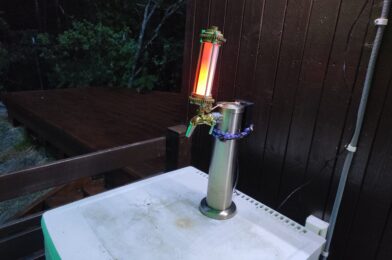
The second light post, tested in twilight.
The second light post I poured came out better, however it was still difficult to keep the concrete between the cut-out and the side intact as it was just so thin. This is a problem that all subsequent light posts also had, and my solution was to try and glue together the bits that fell off as best as I could and treat the lights after they’d been installed with a concrete-repair solution – in other words a problem for future me.
When I knew this method worked well enough, I sat down and made all the parts for the other 4 lights I wanted to make.

Mass producing the parts for the other 4 lights.
Pouring all 6 lights took me around 3 months. Before shipping them off to the cabin I tested them all and made sure to cap off the electrical box so that no water/animals would crawl into them while they were being mounted at the cabin.

The final 2 light posts, standing upside down and ready for transport.
Mounting at the cabin
My hope was that I could simply place the light posts at the cabin in the ground and that the bolt on the bottom of each light post would keep them in place. However when testing this it became apparent that this just would not work, and that they would fall over very easily. So I reverted to more concrete pouring. For this I dug out a hole until I hit the rock bottom. Then I placed large cardboard tubes in the hole, which I filled up with concrete. I also pushed some 20cm long PVC pipe (sealed on each end) in the middle of the drying concrete and held that in place with a brick.


What is the purpose of the PVC pipe you might ask? Well, after a day of drying I would remove the PVC pipe, fill up the hole with fresh concrete and place the light post with its pin inside this fresh concrete, whilst the weight of the light post would be supported by the concrete poured the day before. This allowed me to place the light posts flush with the concrete, and allowed for some adjustment to make them stand exactly straight before the concrete would dry. Genius, right?

This picture shows 4 lights. Can you find them all?
I ended up placing 5 lights. 2 next to the parking space and 3 next to the path. The sixth light has as mentioned some electrical issues, but we might be able to place it elsewhere and powering it using 12VDC.
After putting them up (& waiting 5 months for the winter to pass) I swapped the backplate for a waterproof junction box, and wired them all up using outdoor-rated cabling.

The junction box. Here shown during installation.
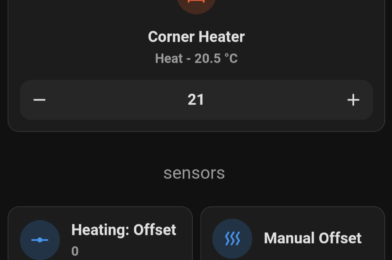
I also installed a 16A Zigbee Mini Smart Switch to control the lights through Home Assistant. This particular version also has the option to add a manual switch, which we might add in the future. Lastly I buried the cable connecting the light posts to a depth of 1-10cm, and after that it was time to wait for twilight and enjoy a job well done.
End result

The first test. They all light up!

In the dark. This is when they look their best.
I really enjoyed this project, even though it took me almost a year to finish it. Not only did I learn a thing or two about concrete, but we now also have some beautiful lights at our cabin, which’ll hopefully stand there for many many years.