This build is based upon the guide from GreatScott! I had seen his video on Youtube back in December 2016 in which he added his own ambilight lighting system to an older TV. In short, ambilights light up the wall behind a TV or other monitor according to what is shown on the TV. This will extend the TV’s colors beyond the actual screen, creating a more immerse viewing experience. Sounded great for gaming!
Back in those days ambilight systems did exist on some premium Philips TV’s, but plug-and-play systems like the Philips Hue Play to add ambilights to your existing TV were not around yet. This project looked very simple and seemed to have a great effect, which is why I also wanted to try it (we’re talking early 2017 here). I was especially curious to see how responsive the LED’s would be, and if they could keep up with fast moving objects on the TV.
The build
For the build we need a few components that are easily sourced through eBay:
- HDMI Splitter.
- 30cm HDMI cable.
- HDMI2AV converter.
- USB Video Grabber.
- APA102 strip which is long enough to go around your TV.
- Power supply.
- Various small wires for data and power distribution.

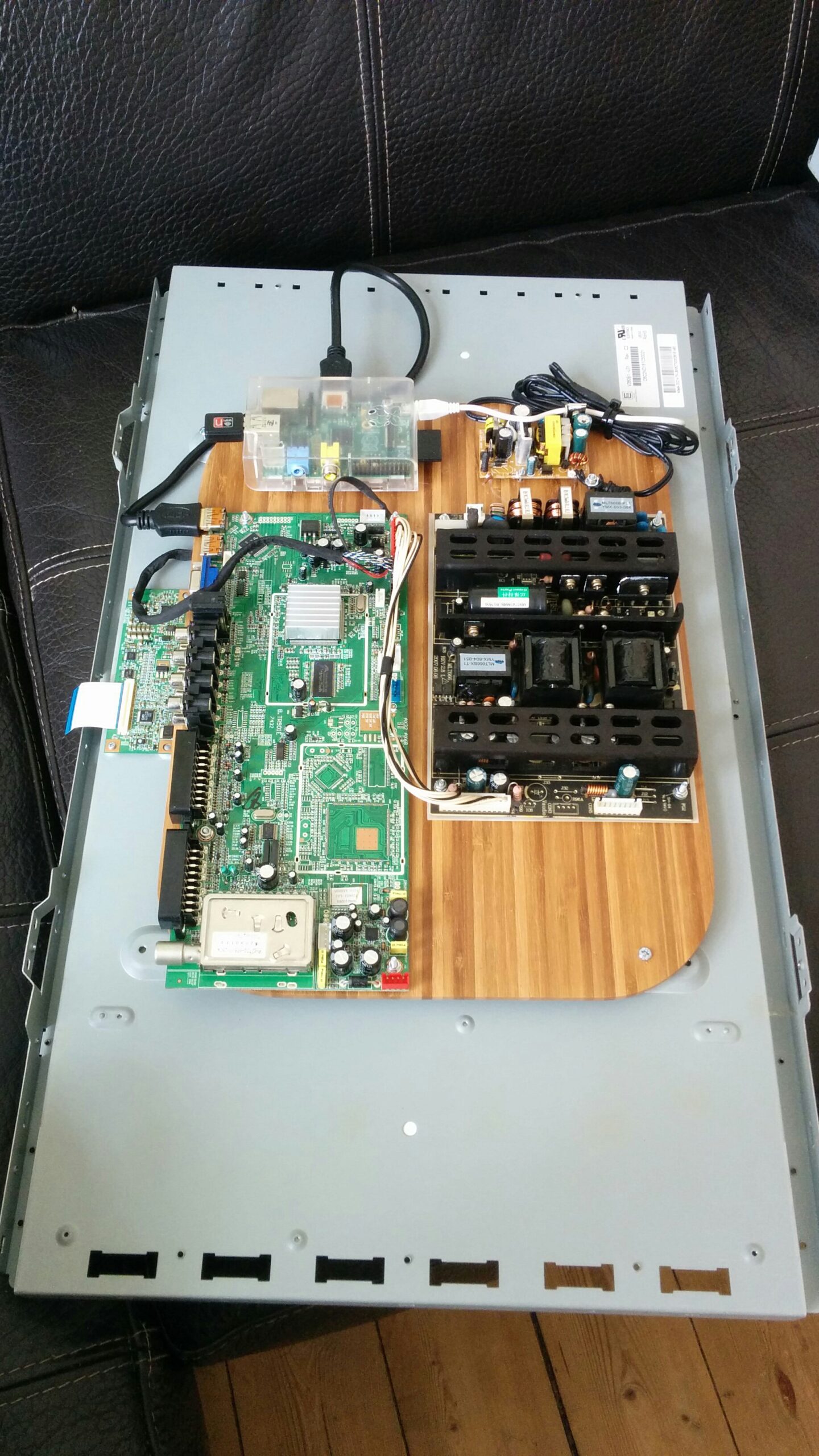
I replaced the Raspberry Pi Zero from the overview for a Raspberry Pi 3 model B, which I had laying around. This also had WiFi built in, which meant I could scrap the separate WiFi receiver.
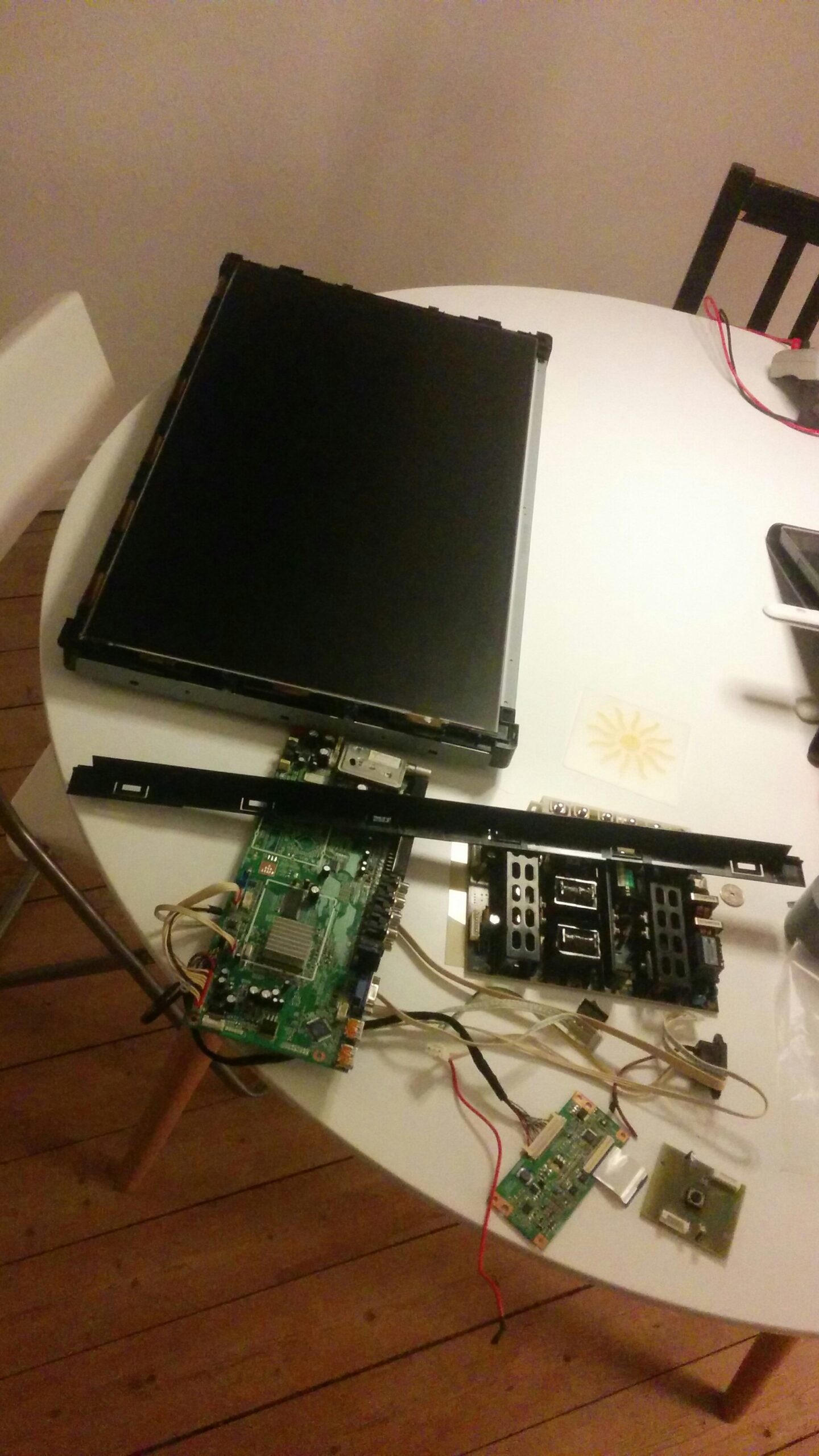
My TV is a 49″ Sharp Aquos, which could house a whopping 194 LED around the edges!

After everything was wired up it was time to set up the Raspberry Pi. Firstly, I downloaded the latest version of Raspbian and flashed this to the SD card. Then I connected it to my WiFi network so I could access it over SSH without the need for an additional Ethernet cable. After this setup was complete I could download and set up HyperCon. This piece of software is truly awesome as it takes care of all the aspects of the project (read out the USB grabber, do the image analytics and controls the LED’s), and in addition provides a remote interface which you can use to show different animations.
Setup is also very easy with the included Configuration Tool. In this tool you can set up the position of your LED’s, configure your grabber and finetune the colors of the LEDs:

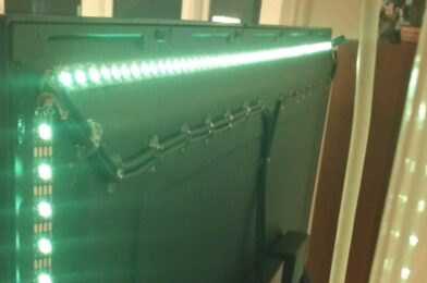
After uploading the configuration file to the Raspberry Pi and starting the included running rainbow animation, which is perfect to run as a test, the result looked like this:

The result
The goal of this project was to increase my gaming experience. For this, the responsiveness of the LEDs needed to be high enough. I never actually measured the response time, but in the video below you can check out the result. As for my own opinion, I think it is more than good enough, especially if I consider that this is a DIY project and offers much more LED’s than the commercially available products back in 2017.
3D printed case
This setup has run without changes for around 2.5 years behind my TV. In September 2018 I wanted to try and design a 3D printable housing which could house both the HDMI splitter, HDMI2AV converter and USB Video Grabber. I came up with the following design:


Unfortunately I don’t have pictures of the end result. It looked good and the setup worked like this for a few months, although I noticed that the housing would get very warm when the system was in use. Eventually either the HDMI2AV board or the USB Video Grabber broke, as the LEDs one day did not came on. I was able to test the HDMI splitter by attaching either outputs to my TV, which showed that it was outputting a signal on both lines. The Raspberry Pi also still worked, as I could control the LED’s via the Hypercon webinterface.
I never came around to fixing this issue, and eventually removed the entire system when we started to use this TV as our main room TV and I got another TV for the gaming.
Would I advice this?
All in all, this is still a relatively easy and fun project. I think it works extremely well for a DIY project, and I would definitely recommend it if you are into gaming or watch a lot of movies, and would like to enhance your viewing experience.