Renovating the balcony

It’s Corona-time! Therefore (almost) everybody has a lot of time at home, including me. In order to make the most out of the situation my girlfriend and I decided it was a good idea to invest some time and money into our balcony as we can see this directly from the living room. During the day this is also the part of the house that gets the most sun as it is located at the south side of the apartment. Renovating this part of the house will therefore allow us to enjoy the outdoor weather during the spring/summer and simultaneously improve the view we have from inside the house.

The first step in renovating the balcony was to make a list of things that needed to be done.

IMG_20200503_103223
IMG_20200503_154832
IMG_20200503_154844

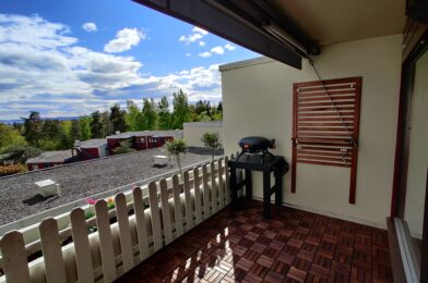
The situation before the renovation

  • The floor was rotten, so that needed to be removed. Underneath the wooden floor were stone tiles, which we decided to leave in place as they made a relatively flat surface, were pretty heavy, and we wouldn’t know if the concrete below would require a lot of maintenance (what you don’t know can’t hurt you).
  • All the grass in the planter needed to be removed to make room for new plants that look better.
  • The walls and planter could do with a paintjob.
  • To make the balcony safe(r) a wooden fence was placed onto the planter. To allow for painting, the fence has to be disassembled, and can then painted as well.
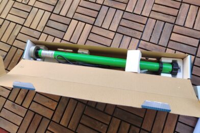
  • There are plans to do a large overhaul on the balconies and planters in this neighborhood in 1-2 years. One option we considered was to build a terrace similar to the one build on the veranda at the other side of the apartment, however this would have to be destroyed if they start the large overhaul. We therefore decided for IKEA RUNNEN decking, which both looked good and is easy to remove again when necessary.
  • Lastly we wanted some nice lounge seats so we could sit outside in the sun.

Preparing the balcony

I started with removing the wooden fences. This was easy as they were hanging on the planter with the help of hooks, and they were only fastened by screws in the bottom. After removing the fence it was time for the grass and the floor. First the grass was gathered in waste bags, after which I cut up the floor in pieces of 90cm (so they would fit perpendicular in the trunk of my car).

IMG_20200503_154844
IMG_20200507_141857

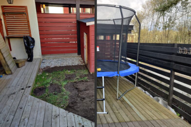
Before and after the floor and grass removal

I then could drive all the old flooring to the local landfill. With everything removed it was the perfect time to paint the walls. Both the red and the white had to be done, so on a nice (semi) sunny day I set to work.

The result after painting red and white.

To determine the color of the fence I made a 3D model of the balcony in Google Sketchup. In our area there are 3 common colors: red, white and brown/black. The 3D model allowed us to quickly change the color to see what looked best:

Balcony_brown
Balcony_red
Balcony_white

In the end, we decided white would look the best. Brown/black made it look like a barcode, while red would not really fit onto the white planter and the trees in the background. We therefore choose to paint the fence white.

The rebuild

It was then time to lay the new floor. The RUNNEN floortiles are very easily clicked into place, and give a very nice result for such a short time. I again made a timelapse of the process, which can be found below:

At this point, we bought some plants and planted those in the planter. After replacing the fence and securing it into place the balcony was almost done.

IMG_20200514_172147

Lounge set

The last thing that was missing was a nice place to sit and enjoy our newly refurbished balcony. After some consideration we again reverted to IKEA, this time to buy an ÄPPLARÖ 4-seat lounge set.

I’m really looking forward to drink a cup of coffee there during the morning, and to enjoy a beer during the evening. The entire family is happy with how it turned out, and hopefully we’ll get a lot of sunny days this year to enjoy the outdoors!

Awning Motor

I bought this 200 watt motor to motorize our awning. This specific model is a Dooya DM45RM tubular motor, which is able to deliver 40 Nm of torque. Hopefully this will pull our 7 meters long sunshade in and out without problems.

As a bonus, it looks like this unit can be connected directly to Homey, which also means a Google Home integration (via Homey) is possible (‘Hey Google, give us some shadow’). I’m looking forward to install this bad boy!

Home NAS Server Setup

This website runs on an Intel NUC.

Actually, a lot of things are now running on this little NUC. Before showing you exactly what processes/services are running, please allow me to explain why I have this NUC in the first place.

Home Assistant and the NUC

In our previous house I was running Home Assistant on a Raspberry Pi. Home Assistant is a piece of software that can observe, control and automate nearly anything that can be part of a smart home. In my case, I had the following devices connected to it:

Linking all these devices together required something more robust than a Raspberry Pi, hence why in April 2019 I bought an Intel NUC NUC6CAYH. This little fellah has an Intel Cerion CPU, place for a maximum of 2x 4GB of DDR3L RAM, can house a 2.5″ hard drive and has a 1Gb ethernet port. I figured that this was a very good alternative for a Raspberry Pi, whilst also keeping my wallet in mind.

This NUC ran Home Assistant (or HA for short) very reliably, although the HA software itself needed quite some maintenance, up until we moved in December 2019. The NUC disappeared in a box, and at the new house I bought an Athom Homey to take over the task of HA in an attempt to limit the amount of maintenance work. This is why I had a NUC laying around when I decided to start setting up a Home Server in January 2020.

First step: Setting up a NAS file server

When I started on this project I knew nothing about file- or NAS servers, but I imagined that there would be open source software out there that could help me out. I had decided that I did not want to buy new hardware, as things could be tested on the NUC first to see if it would be good enough.

Two names that kept popping up were FreeNAS and Unraid. They both looked equally good candidates for me, so I picked the one that felt like it had the best chance of succeeding -> FreeNAS. Over the last couple of months I have been very happy with this choice. FreeNAS is running very stable and is in my opinion easy to use. The initial file server setup was a breeze, and in no-time I had a functioning NAS server which could be accessed through a PC with Windows Explorer (via a Samba share).

FreeNAS has a functionality which are called ‘Jails’. Jails are, very shortly explained, little isolated operating systems that use the same kernel as the hosts operating system. This means that they are more lightweight to run than a Virtual Machine as they dynamically share available RAM, CPU & HDD space between the host and other jails, but simultaneously are compartmentalized from the host. Processes run inside the jail can only access files inside the jail, and processes/files inside the jail are not aware of any file outside the jail. An additional (much better) introduction to jails can be found here. All in all, they are a perfect place to run additional programs/services without the risk of breaking my entire NAS system.

The current setup

The current HW setup, including PS4 Pro and Philips Hue bridge

Hardware

The current hardware today is, as I mentioned, running on an Intel NUC. This includes:

The HDD’s are set up in a mirrored configuration. That means that all data is copied on both drives, giving me an effective storage capacity of 2 TB whilst also protecting myself from a disk failure. This is also called a RAID 1 setup.

FreeNAS Software setup

The current setup is running 3 jails, 1 Virtual Machine, a samba share and some additional smaller services inside FreeNAS:

FreeNAS services setup
  • The Samba share allows us to access files on the server when we’re on the home network.
  • The website that you see right now is running inside a Jail.
  • A second jail contains NextCloud. NextCloud mainly allows for automatic synchronization of pictures and videos from my phone to the server.
  • Since there are multiple websites that I want to access from this web-address there is a jail set up that acts as a Reverse Proxy server.
  • Lastly I have a virtual machine that runs PiHole. PiHole is software that blocks advertisements on my home network. Unfortunately it cannot run (yet) inside a FreeNAS jail as it does not support FreeBSD, the operating system FreeNAS runs on.

So how do all these services work together? Well, that’s a different view:

Networking flow

Starting from the bottom, there are the NextCloud storage, this blog and the magic mirror which are accessible through the internet via the reverse proxy. There is also the Samba share which is accessible only on the local network for privacy reasons.

In the middle of the picture is the router which obviously has access to the internet. All DNS requests are however forwarded to PiHole. A DNS request is a request for a name server to translate the domain name of a website (for example jessendelft.org) to an address (for example 217.197.166.65), in order to connect to that address. PiHole blocks any requests to known advertisement addresses so that these requests never get resolved, which means they will not load. This way there is network-wide ad-blocking for all devices connected to it.

I have some plans of integrating Octoprint into the Reverse Proxy once my 3D printer is back up&running. I also want to move PiHole to a jail to free up some RAM and HDD space which are now reserved by the Virtual Machine.
If you have any more ideas on what I can do to improve my setup, please let me know!

Installed a mesh WiFi network

Yesterday I bought this ASUS RT-AC66U router with 2x Lyra Trio routers. These together form a mesh network at my home, giving me a whopping 1.3 GB/s of theoretical speed on the 5GHz network.

Top Gun I Feel The Need GIF - Find & Share on GIPHY

So how much do I actually get? My subscription should allow for 600/600Mbps. The following is measured on the 5GHz WiFi in the living room while the access router is a few rooms away.

It’s not 1.3 GB/s, but for a Wi-Fi connection this is not bad at all.

Still, I wanted to try and reach the maximum that I’m paying for. So in the next measurement I turned off the QOS settings in the router (to prevent it from reserving bandwidth for other services), and attached my PC to one of the LAN ports. The results speak for themselves:

So hopefully this should allow us for problem free streaming, downloading, gaming and video calling during the current Corona lockdown.

Ambilight System

This build is based upon the guide from GreatScott! I had seen his video on Youtube back in December 2016 in which he added his own ambilight lighting system to an older TV. In short, ambilights light up the wall behind a TV or other monitor according to what is shown on the TV. This will extend the TV’s colors beyond the actual screen, creating a more immerse viewing experience. Sounded great for gaming!

Back in those days ambilight systems did exist on some premium Philips TV’s, but plug-and-play systems like the Philips Hue Play to add ambilights to your existing TV were not around yet. This project looked very simple and seemed to have a great effect, which is why I also wanted to try it (we’re talking early 2017 here). I was especially curious to see how responsive the LED’s would be, and if they could keep up with fast moving objects on the TV.

The build

For the build we need a few components that are easily sourced through eBay:

  • HDMI Splitter.
  • 30cm HDMI cable.
  • HDMI2AV converter.
  • USB Video Grabber.
  • APA102 strip which is long enough to go around your TV.
  • Power supply.
  • Various small wires for data and power distribution.
Schematic overview of components, borrowed from GreatScott!

I replaced the Raspberry Pi Zero from the overview for a Raspberry Pi 3 model B, which I had laying around. This also had WiFi built in, which meant I could scrap the separate WiFi receiver.

My TV is a 49″ Sharp Aquos, which could house a whopping 194 LED around the edges!

Installation of the components. The LED strip, Power supply, Raspberry Pi, and HDMI splitter are in place, as well as a power distribution box.

After everything was wired up it was time to set up the Raspberry Pi. Firstly, I downloaded the latest version of Raspbian and flashed this to the SD card. Then I connected it to my WiFi network so I could access it over SSH without the need for an additional Ethernet cable. After this setup was complete I could download and set up HyperCon. This piece of software is truly awesome as it takes care of all the aspects of the project (read out the USB grabber, do the image analytics and controls the LED’s), and in addition provides a remote interface which you can use to show different animations.

Setup is also very easy with the included Configuration Tool. In this tool you can set up the position of your LED’s, configure your grabber and finetune the colors of the LEDs:

HyperCon configuration tool, showing my specific LED setup.

After uploading the configuration file to the Raspberry Pi and starting the included running rainbow animation, which is perfect to run as a test, the result looked like this:

HyperCon Rainbow test. Looking fancy already!

The result

The goal of this project was to increase my gaming experience. For this, the responsiveness of the LEDs needed to be high enough. I never actually measured the response time, but in the video below you can check out the result. As for my own opinion, I think it is more than good enough, especially if I consider that this is a DIY project and offers much more LED’s than the commercially available products back in 2017.

3D printed case

This setup has run without changes for around 2.5 years behind my TV. In September 2018 I wanted to try and design a 3D printable housing which could house both the HDMI splitter, HDMI2AV converter and USB Video Grabber. I came up with the following design:

Case V1 v10
Case V1 v11

Unfortunately I don’t have pictures of the end result. It looked good and the setup worked like this for a few months, although I noticed that the housing would get very warm when the system was in use. Eventually either the HDMI2AV board or the USB Video Grabber broke, as the LEDs one day did not came on. I was able to test the HDMI splitter by attaching either outputs to my TV, which showed that it was outputting a signal on both lines. The Raspberry Pi also still worked, as I could control the LED’s via the Hypercon webinterface.

I never came around to fixing this issue, and eventually removed the entire system when we started to use this TV as our main room TV and I got another TV for the gaming.

Would I advice this?

All in all, this is still a relatively easy and fun project. I think it works extremely well for a DIY project, and I would definitely recommend it if you are into gaming or watch a lot of movies, and would like to enhance your viewing experience.

Tagged : / / /

Building a terrace

We recently moved to a new house. This house has a veranda, which included a terrace that covered ~60% of the total area. The rest was covered by some (poorly grown) grass and a small playhouse for the children.

Overview of the veranda

Our plan is to extend the terrace to cover at least all the grass for 2 reasons:

  • The grass’s condition is really poor, and there are a lot of small stones. We have a baby that soon will start to crawl around, and don’t want her to hurt herself on the stones or start eating the grass.
  • We have a second child which is almost 11, who would love a trampoline.

To determine the amount of materials needed for this job (and to have a good reference), I measured the veranda and drew it into Google Sketchup:

3D model of the veranda

The most common small-sized trampolines we can buy in our local stores are 3 meters in diameter. Inside the 3D model I drew a 3 meter wide trampoline and saw that it would just about fit in the middle of the veranda once the terrace was build. It would however be a tight fit with the children’s playhouse and the project that I’m planning on the left side of the veranda.

With this in mind we planned to see how things worked out by leaving the children’s playhouse intact and start building the terrace.

The build

Firstly, I removed the grass, stones and started digging holes which would later be filled with gravel to support the terrace.

Our first thought was to save ourselves some work and leave the playhouse intact, building the new terrace around it. Around halfway into the digging, we decided that this lazy approach was not the right way to do it. It would be better to build the terrace all the way, to allow the playhouse to be placed more freely afterwards. Below is a video of how this process looked.

Digging the holes was hard work, as the ground was quite wet and felt like clay. But after a week of digging, everything was removed and the part that I’m really diggin’ (badum-tss), namely the building part, could start!

I’m diggin’ it!

I got some help from my brother- and father-in-law who were kind enough to buy me the building materials and drive them to our house. I also need to thank them for loaning me much of the equipment I needed for this build. So thank you!

Placing anti-root fabric and gravel

After placing the support structure, the final layer of wood could be build. While doing this I attempted for the first time to make a time-lapse video, which turned out exceptionally well.

And when all the sawing, screwing and building was done the end result looks like this:

Jump! Jump! Jump!

Magic Mirror Build #3 – Upgrades

Since I originally built my mirror it received multiple upgrades, both in hardware and in software. In this post, I will attempt to describe the changes I have done over the years.

Modifying the original software

As I mentioned earlier the first software that I installed was the original MagicMirror software by Michael Teeuw. This software was able to show the following things:

  • The time
  • The weather
  • Compliments
  • News headlines

This of course was already very nice. However, I wanted to make the software a bit more my own. I therefore modified it to include a line which showed the song I listened to last. This was managed by linking up my Spotify with Last.fm. Spotify would ‘scrobble’ (a fancy word for logging) the song to Last.fm. The mirror would poll (ask) Last.fm every 10 seconds which song was scrobbled last and display this on the mirror. The end result looked like this:

2015-10-06 16.50.59

Me being happy with my first mirror!

Upgrading the hardware

The original mirror had a Raspberry Pi 1 model B to show the content of the screen. The reason I didn’t have the Raspberry Pi 2 even though it was released in February 2015, was that I had actually salvaged the RPi 1b from another project. A year earlier (April 2014), I had tried to set up a media server/TV receiver inside a beer-crate that I had rebuild into a boombox:

2014-04-01 12.41.37
2014-04-01 12.45.29
2014-04-01 12.46.14

However due to the weight of the screen & Raspberry Pi, and limited reception due to the fact that I could not fit a large enough antenna, I decided to scrap this part of the boombox.

Using the Raspberry Pi 1 model B in the mirror was fine, as it was also running the original Magic Mirror software (not yet MagicMirror²). This original hardware setup ran for about 2 years, way into 2017.

2017 – New software, new Raspberry Pi

In 2017 I revisited the project and found out about the new MagicMirror² software. Firstly I decided the RPi 1b has had it’s best time, and it was time to replace this with a new Raspberry Pi 3 (not really for any good reason, but just because I wanted something fancier). Secondly, I installed the new software on the mirror, which allowed me to do much more with the system, as this new software relied on modules that could easily be added and/or removed from the system. This meant that first of all, there were now a whole lot of people around the world collaborating on this project and making fancy modules that could do all sorts of things. Secondly, since the structure of the software was greatly improved, it became much easier to add, edit and maintain the entire setup.

raspberry-pi-2011-12-arm-board_e041ffb858d0a3b7b064d32c150c7aae
raspeberry-pi-3-b-plus_048517a8fc3655104ecd437aa38d9511

Raspberry Pi 1 model B vs. Raspberry Pi 3B+

Later, after it came out, I upgraded the Raspberry Pi again to a 3B+. Since I updated to MagicMirror² I have tried many different modules, although I never wrote them on a list and most of them I have therefore also forgotten again.

February 2019 – Screen update

Ever since I build the mirror I wasn’t very satisfied with the original TV screen. The resolution of the screen was 720p, and since it was such an old TV I imagined it used quite a lot of power. I have a BenQ G2412HD that I have used as a second PC monitor for years which has performed extremely well in my opinion. It also has physical buttons to control the screen, which means they are probably mounted on a separate PCB and easy to put it in a new case. So, a perfect candidate for me to replace the TV screen with.

I did not want to use my own screen for this (just in case I messed up and ended up with no screen at all). Luckily I was able to find one second-handed online. It had glue residues on the side, which obviously did not matter to me (the original casing would be removed anyway).

Second-hand BenQ G2412HD

Replacing the screen turned out to be easier than expected. This was mostly because there were not really any unforeseen challenges. Everything was screwed/clamped together (no glue was used inside), and the buttons were placed on a separate circuit board which made it easy to extract and relocate them.

To mount the new screen and aluminium box that contained the screen control board in the case, I designed and 3D printed a small bracket which was able to hold the aluminium box in place inside the mirror’s case.

Design of the 3D printed bracket

I had also the wish to move the location of the Raspberry Pi. In the old setup the Raspberry Pi was located on the top. This meant that the heat produced by the TV screen would pass by and heat up the Raspberry Pi, and it would often operate at +60ºC. In the new setup the Raspberry Pi sits in the bottom of the screen inside an aluminium box (which houses all the other electronics as well), which means that cooler air is used to cool the Raspberry Pi and should thus reduce the operating temperature.

2015-10-02 23.21.41_rpi
IMG_20200422_132552_cut

Old vs. new backside. The location of the Raspberry Pi is shown with a red square.

With the Raspberry Pi in the bottom the operating temperature dropped down to ~50ºC while operating.

As mentioned, all the electronics of the new screen are located inside an aluminium box. This box came with the BenQ screen and turned out to be higher than the old TV control board, which meant I had to extend the case a bit. To achieve this, 4 small wooden blocks were placed in the corners of the mirror. I believe this also improves overall cooling of the system, as it allows more air to flow past the back of the mirror.

With all the changes the front side also looked different:

2015-10-06 16.51.08
71703325_2749199848426233_4822439737224593408_o

Old vs. new frontside

I was quite blown away by the difference a 1080p screen makes. Suddenly, the clarity was much better and I had to increase some of the fonts because they were too small to read.

Current setup

To showcase the mirror to people when I’m not at home, I have set up two instances of the Magic Mirror software. The first one is only accessible by the local filesystem and takes care of everything that is being shown on the physical mirror. The second one is running in ‘server only’ mode, and can be accessed over the internet. This remote one has some more restrictions, and much of my private information has been removed.


Check out the remote instance here

My current (local) setup consists of the following modules:

As a finisher, I’ll show you how all of that together looks:

Cheers!

Magic Mirror Build #2 – Getting things to work

After having learned from my Previous Attempt, I now decided it was best to take some smaller steps. I still had the Raspberry Pi, and was quickly able to buy another old TV for very cheap. I moved this TV in a similar fashion as previously, but this time I would focus on getting the software up&running first.

The first test

Installing the software wasn’t very difficult, I just had to Follow Michael Teeuw’s guide on how to set up the Raspberry, and then Install his software. After having done this, I found myself looking at a copy of the Magic Mirror!

Hooray, something works!

I then tried the cheap eBay foil again. Still, the results I got from this were far from satisfying. It looks like I’m going to have to pull out my wallet and get myself a real one-way mirror…

Second time trying the cheap eBay foil. Again, not a satisfying result.

The frame

Now that I had ordered a real mirror (bey bey savings), I had some time left to focus on the aesthetics of my mirror. So, I removed the casing of the TV and tried to build a decent looking frame around it.

Building the case

I was quite impressed with how this looked, and after a paintjob I was getting quite happy with it.

Wrap up & result

Now, it was only a matter of waiting for my mirror. When that finally came in, I could screw/glue it all together, and I had myself a Magic Mirror!

You look sexy!

Check out the updates here!

Magic Mirror Build #1 – First Attempt

In June 2015 I stumbled upon a blogpost by Michael Teeuw, the creator of the original Magic Mirror. He holds a blog at michaelteeuw.nl called Xonay Labs. Admittedly, most of my current website is inspired by his website, but as a starter this was the first project I also decided to attempt. If you haven’t seen it, take a look at his original project and blog, I’m sure that if you like the stuff I’m doing, you’ll love his site!

So, let’s get to the build:

July 2015 – First Build

A magic mirror works by having a screen behind a so called one-way mirror. A one-way mirror reflects a certain percentage of the light that hits it, while it also lets some of it through. This means that if we put a one-way mirror in front of a display and display some white text on a black background, the text will shine through the mirror and shows up between our reflection! Awesome, right?


There are a few things we’re gonna need for this build:

  • A Raspberry Pi to run the software (which we again will credit to Michael Teeuw).
  • A display to tell us how sexy we look today.
  • A one-way mirror.

Also, being a student at the time meant that I wanted to do this project as cheap as possible. So first, I ordered myself some one-way mirror foil on eBay (which was €5,- compared to an actual mirror that costed €200,-). In addition, I bought a Raspberry Pi and an old TV-screen that I picked up using my motorbike:

Very professional transportation of the TV screen.

Being very (over-)confident of myself, I decided that I’d be able to take apart the TV and different layers of the LCD panel, and glue the foil right onto the top layer of the LCD panel. The disassembly went rather well, but after I glued the foil on the display I was rather disappointed with the mirror-effect. Also, after I assembled the TV back together I found that the LCD panel was broken.

Here I found out that this project is going to take some re-work and smaller steps…

Check out part 2 here!

Tagged : / / /